Sidebar
Action disabled: source
astra_conv:conversion:traction_battery:traction_battery
Table of Contents
traction battery
lead-acid traction battery
Before I got my LiFePO4 cells, I provisionally used a set of Hawker SBS60 12V 50Ah AGM batteries.
Although their designated service life time had already expired, they did surprisingly well - so I feel they should be perpetuated here!
Batteries paralleled (the use of fuses might have had some charm) for easy charging.

Batteries provisionally arranged in the rear battery box, connected in series. Note that here, for maintenance, the circuit is broken up at two different places. When interrupting it at one place only, you will encounter the full traction voltage at this point, so you are still not safe!

lead-acid lab charger
Commercial charger - meanwhile quite old-fashioned - that I some years ago modified to display voltage and current. It now further allows to choose between two maximum voltages and the original (quite useless) “automatic program”. Although it misses the intelligence and power of today's chargers, it is still quite useful because it tells you what is actually going on with the battery.

lithium traction battery
With its atomic mass of only 6.941, Lithium is the most lightweight metal on earth.
260 kilograms of it however may still be too much for an aged palette.

After six months of waiting, the cells (30 pieces Winston LYP260AH) finally hade arrived, well protected in nice wooden boxes. Each box came with its own certificate.


Stainless steel M12 bolts, washers and spring-lock washers were also included, together with 5-layered 55mm copper jumpers. Quite some weight, by the way …

Lithium single cell charger
When taking the battery into operation for the first time, the cells may not be at uniform state-of-charge. The battery management system will attempt to balance the cells by shunting those who reach HVC (high voltage cutoff) first, but this will not be sufficient in case of a larger imbalance.
The battery manufacturer recommends an initialization charge for every cell, to ensure that all cells are at equal state-of-charge. Each cell will be charged to the same voltage, at a “steep” section of the voltage - vs. - state-of-charge curve. This proceeding is referred to as “top balancing”, because balancing is performed at the highest possible state-of-charge of each cell.
On the web site of the BMS manufacturer, very advisable instructions for top balancing can be found.
My single-cell charger helps to do top balancing according to these instructions, in an half-automated way. It connects to both the analog remote-control input of a lab power supply and to the battery management system (BMS) cell loop. The cells can be balanced after they have been built into their battery box and connected to each other, and with the BMS already in place. This is useful since in order to save time, it is advisable to first charge the battery normally with the car's traction battery charger, and then only top-up the missing charge for each cell to reach HVC. The cells initially come at a low state-of-charge, so charging them with a lab power supply alone might otherwise easily take 10 or more hours per cell!
Note that it is also not adivsable to handle cells that are fully charged, trivially because then they release most energy when accidentially shorted.
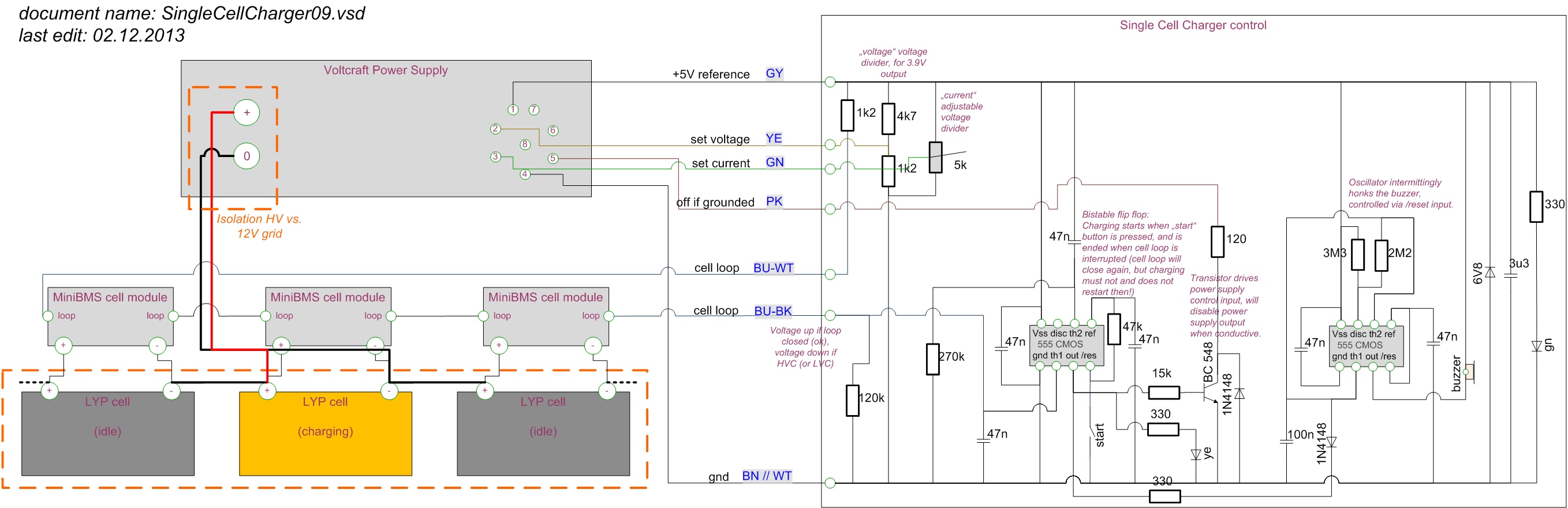
The diagram shows the circuitry of the “Li single cell charger”.

The left side of the diagram shows the chain of lithium cells with attached BMS modules and a lab power supply.

The dashed orange rectangles indicate the “isolation” border between HV and 12V grid. For the lab power supply (the grey rectancle in the top left), this means that it's output must be floating, without reference to control inputs, protective ground or the power supply's case.
The lab power supply (Voltcraft PPS11810) can be remote-controlled digitally via a serial interface accessible via USB. For modernization losers like me however, the device also provides an analog input that allows to set target voltage and maximum current via resistors, and to switch the output to high impedance via an external switch.
Below the power supply, the chain of cells is shown, each cell with it's BMS cell module on top.
The right side of the diagram shows the circuitry of the small plastic box.

The +5V reference output of the lab power supply is abused to supply the circuits in the plastic box.
The power supply device's inputs “set voltage” and “set current” are served by resistive voltage dividers. For the voltage, there is a fixed setting of slightly below 4.0 volts, which is higher than the cell modules' HVC (high voltage cutoff) around 3.65V, but still below the critical voltage for the cells. The cells will normally not exceed the HVC voltage, but as an extra safety precaution the power supply's idle voltage should not be chosen higher than 4.0V.
The low voltage margin of course requires thick jumper wires, otherwise their voltage drop would prevent that the maximum current is (more or less) sustained till the end of the charge, and thus slow down the charging process. What a surprise, by the way: This is what you get when you buy a € 4.- jump lead set. Right side: the original wire of the jump leads. Left side: 10mm² gauge wire, for comparison …

The current is adjustable between 0 and maximum (>10A). It must be taken care that the power supply can constantly deliver the chosen current. Luckily, mine turned out to easily deliver its maximum rated current of 10A, without even getting noticeably warm.
Of the two old-fashioned timers in the diagram, the one to the left acts as a bistable flip flop: When the device is powered up or the “start” button is pressed, the lab power supply's output will be enabled. As soon as the cell loop opens, the output will be disabled, and it keeps disabled also when, after a few seconds, the voltage falls below HVC and the BMS module closes the cell loop again. So, charging is terminated and will not be resumed, once HVC has been reached.
The right timer will intermittingly ring a buzzer to signal that balancing of this particular cell is finished.
When it is well ensured that the power supply has a floating output, it can be connected to the cell terminals without taking the cells out of the HV grid.
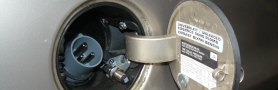
Top view of the device, with the remote-control connector towards the lab power supply.

Device connected to the lab power supply. The green LED within the plastic box just indicates that power is present, the yellow LED signals that the device currently has disabled the power supply's output.
On the power supply, the yellow LED “rear control” is lit, indicating correct setting of a switch at it's rear. The jump leads are connected to the rear output of the power supply, since the front output has insufficient current rating.

Power supply connected to cell in the front and rear traction battery box, respectively. Note that due to the voltage drop on the jumper cables at this current, the voltage on the power supply inevitably exceeds the cell voltage. On the second picture e.g., the cell voltage is just approaching the HVC voltage near 3.7V, while the power supply displays 4.0V.


This is now the “balancing” procedure: Connect the jumper leads to a certain cell, press the “reset” button on the plastic box and wait for the beeper to come up.
Then connect the jumper leads to the next cell, wait a few seconds for the previous BMS cell module to close the cell loop and reset the plastic box again. At 10A charging current, each cell took between 10 and 50 minutes, with an average around 25 minutes, to reach HVC.
astra_conv/conversion/traction_battery/traction_battery.txt · Last modified: 2014/05/03 23:57 by richard
Except where otherwise noted, content on this wiki is licensed under the following license: CC Attribution-Share Alike 4.0 International
