
Sidebar
astra_conv:conversion:wiring_logics:wiring_logics
Table of Contents
wiring - logics
Another thing that I would have tackled differently á posteriori is the implementation of all the logics that connect the different state and alarm signals and control inputs. While at the beginning of the project, their number and also their interdependence seemed easily manageable, the complexity increased over time.
So, my approach of using e.g. some combiner diodes to form a logical “OR”, to feed signals to both ends of a relay coil for an “A AND NOT B” or to use old-fashioned timer circuits eventually ended up in quite a messy harness of wires and circuit boards.
I did use a few microcontrollers (heater control, control of the cooling system, DC/DC converter control), but not a central processor - which would for sure have made the setup much tidier and easier to manage.
alarms
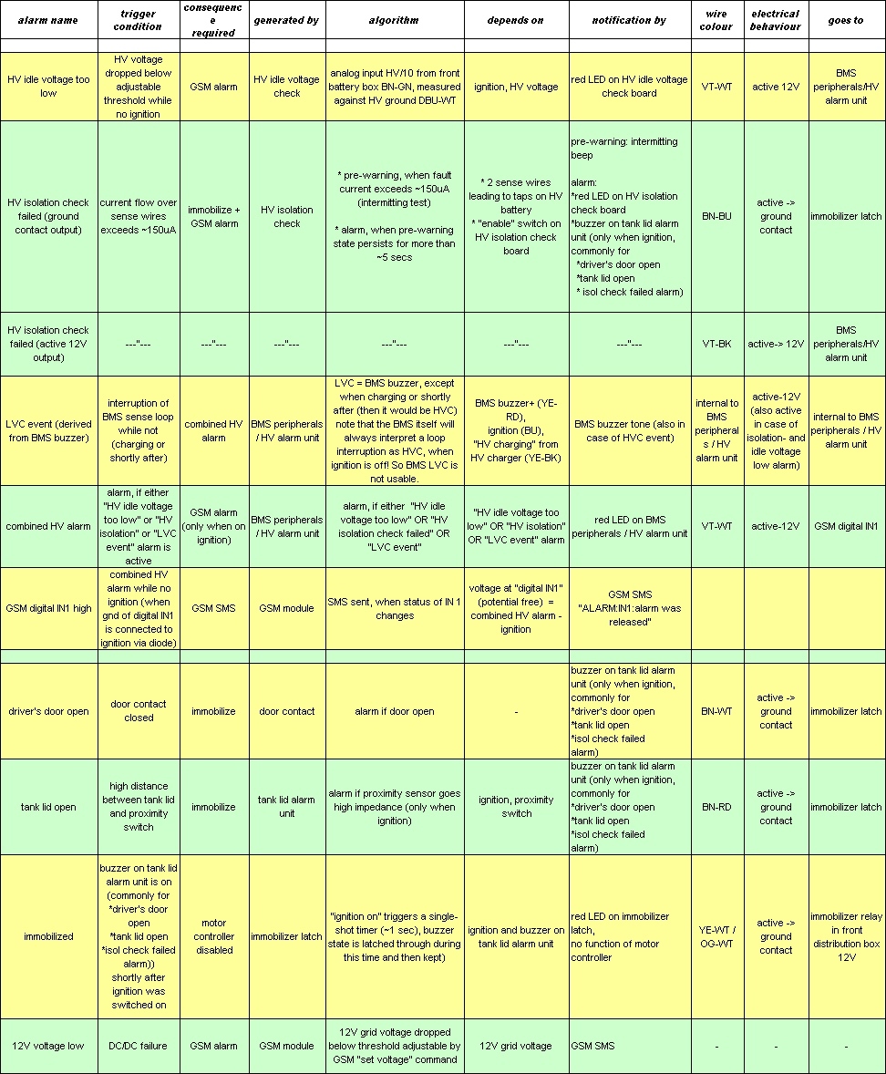
Following table shows the numerous alarms that have to be handled somehow, and their connection to control lines or logics circuits. Each row covers one alarm. “Trigger condition” means the condition upon which the alarm is raised. In column “goes to” we see to which destination the alarm is connected. For example, the “HV idle voltage too low” alarm (first row) connects to the “HV alarm unit” on the “BMS peripherals” circuit board. This circuit will raise the “combined HV alarm”, with “HV idle voltage too low” as one possible trigger (see column B).
As another example, the “HV isolation check failed” alarm generated by the HV isolation check board actually provides one “ground contact” and one “active 12V” output. The ground contact output goes to the immobilizer latch (which avoids that the immobilizer is triggered during driving), while the “active 12V” output again is fed to the HV alarm unit of the BMS peripherals board.

link to alarms table (jpg), right-click and save as file (or directly open with a picture viewer)
BMS peripherals board
The BMS peripherals board, which is located in the rear distribution box, comprises three rather independent circuits that cover different logics tasks. They however share some power supply and signal inputs.
Please see the circuit diagram and a view of the circuit board below. A top view of the board with explanations of the different terminals and LEDs is provided in the chapter "trunk distribution box"“.


charger lock
This “circuit” is actually only a small conventional relay. It opens the 20mA loop of the HV battery charger und thus disables the device when ignition is on. This shall avoid overcharging of individual traction battery cells: While ignition is on, the BMS system is not able to correctly detect “high voltage threshold crossed” events, but wrongly interprets them as “low voltage threshold crossed” events. Therefore, BMS will not shut down the charger in time while ignition is on.
HV battery alarm
The HV battery alarm implements some of the logic relations listed in above table.
It generates a “HV battery alarm” signal that is fed to the digital input of the GSM module, to warn of a serious condition of the traction battery:
* HV idle voltage alarm (HV voltage too low, while ignition is off)
OR
* isolation alarm
OR
* BMS alarm occurred, but the HV battery charger is not on (or has been charging recently). While charging and shortly after, a BMS alarm can only mean “high voltage threshold crossed”, which is handled by the battery charger and does not require manual intervention. Else, a BMS alarm will mean that the low voltage threshold has been crossed at at least one cell.
I however later changed the timer in this circuit to a very short time (a few seconds), so that it is without effect and now both events will lead to an HV battery alarm.
DC/DC control / 12V recharger
This microcontroller circuit, based on a Microchip PIC16F690, controls the DC/DC converter (only “on” and “off”). It switches the DC/DC converter on while ignition is on, if the voltage of the battery has dropped below 12,6V or after some idle time has expired. In case of a HV battery alarm, the DC/DC converter will not be run to avoid deep discharge of the HV battery.
Since I had difficulties implementing interrupts (some memory allocation problem), the program is implemented in a dirty way by some loops and polling of external conditions.
In paticular, the behaviour is
a SOC (state-of-charge) counter mimicks the SOC (only the uppermost few per cents of it) of the 12V battery.
The program cycles in either “charging” or “idle” loop.
in charging loop: yellow LED = “recharge” output is on (RC6 high) SOC is increased by <charge_fac> (variable) every <period> cycles
in idle loop: yellow LED = “recharge” output is off (RC6 low) SOC is decreased by 1 every <period> cycles
charging state is entered when * SOC reaches 0
idle state is entered when * SOC overruns 255
* if voltage drops below threshold: set SOC to 0, set RC7 = bright red LED threshold trigger forces output to “on” (rapidly sets SOC to minimum)
* if ignition on (RB4 high) OR “HV charging” (RB5 high): set yellow LED = “recharge” output is on (RC6 high) increase SOC by <charge_fac> ignition and “HV charging” increases SOC at normal charging speed
* while combined HV alarm is high (RB7 high): clear yellow LED = “recharge” output (RC6 low) keep SOC at 255, stay in exception loop BMS buzzer and HV_idle alarm: rapidly increases SOC to maximum (to save HV battery with priority)
astra_conv/conversion/wiring_logics/wiring_logics.txt · Last modified: 2014/05/20 17:45 by richard
Except where otherwise noted, content on this wiki is licensed under the following license: CC Attribution-Share Alike 4.0 International
