Sidebar
Table of Contents
coolant heater
introduction
As already mentioned in the chapter “conversion - heater”, heating with the car's original ventilation system and heat exchanger requires an appliance that heats up the coolant liquid. In addition, an electric pump is required to circulate the fluid between the heater and the dashboard heat exchanger.
If operated electrically, such a heater must be powered directly from the traction circuit, while the 12V grid delivers much too little sustained power.
I decided - and later I frequently regretted - to build my own heater for this purpose. I had seen very low-priced power MOSFETs with a maximum dissipated power up to 600 Watts. Such semiconductors surprisingly are much cheaper than power resistors suitable for heat-sink mount.
The idea was to bolt a couple of those MOSFETs to a heat exchanger that it passed by the coolant liquid. By applying gate voltage in a very gentle and controlled way, it should be possible to run them more or less directly between the traction circuit's rails, with only small negative feed-back source resistors required for stabilizing.
To reveal in advance - the concept did finally work out. However, there are some restrictions that made the thing become quite complex and expensive:
- Power MOSFETs have a maximum rated junction temperature in the range of 150°C. For proper heating, a coolant temperature up to 80°C (my estimation, after some tests) is required. At this low differential temperature, and even with very low heat transition resistance, the maximum dissipated power is strongly reduced.
When the heater is just started up and the coolant liquid is still cold, it can initially run at much higher power. Same applies to extremely low ambient temperature, where the maximum coolant temperature just cannot be reached. To optimize performance, a “derating” must therefore be applied that limits the dissipated power as a function of the heat exchanger's temperature.
- Meanwhile, there are terrific heat conductive pads on the market, with very low specific heat resistance at high mechanical durability and reliable electrical isolation. However, you will never know the exact junction-to-heat-exchanger heat resistance for your transistor. Neither is it possible to directly sense the junction temperature. Finally, you must take into account possible ageing effects. Therefore, you must plan it a lot of reserves when dimensioning the circuits, so you cannot utilize the maximum power.
- The MOSFETs that I used turned out to have a very high spread of gate-source voltage, referred to equal drain current. This required much larger source resistors for negative feed-back, and still every MOSFET requires its individual adjustment resistor to balance out the dissipated power. Remaning imbalance also impacts the overall heat output.
- With drain directly attached to the traction circuit's positive rail, there is no protection against overcurrent in case that once the transistor is steered too far into the conductive range. This might happen by a glitch in the gate voltage or by thermal runaway (in case the control circuit cannot react quickly enough). A glitch in the gate voltage might e.g. sneak in from the traction circuit via the transistor's parasitic drain-gate capacitance.
After some bad experience, I have added heat-sink mountable drain resistors that limit the maximum current and also contribute to the dissipated power. Unfortunately, such resistors are more expensive than power semiconductors.
circuitry
overview
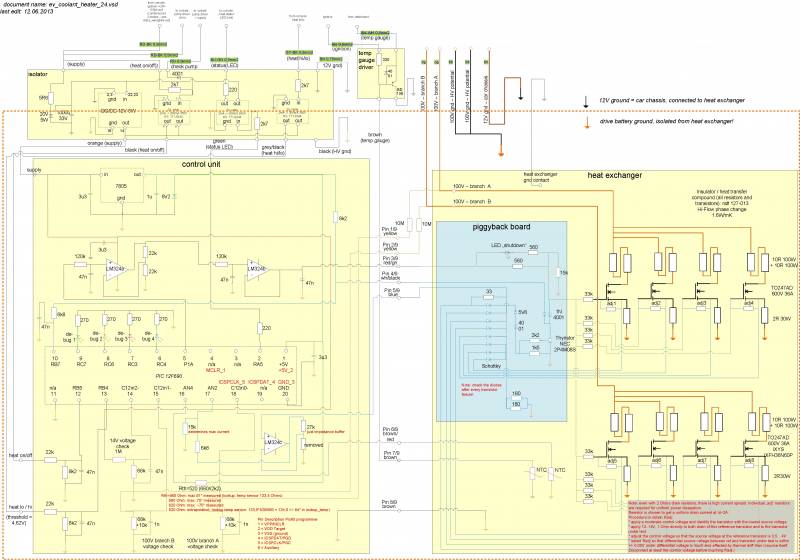
The heater's circuitry is shown in below picture. The link below allows to download and view the diagram in full resolution.
link to wiring drawing (jpg), right-click and save as file (or directly open with a picture viewer)
Main parts are the heat exchanger with it's attached power transistors to the right, and the control unit to the left.
The heat exchanger also carries a small piggyback board with a diode combiner for the feed-back branch, and a thyristor crowbar circuit for emergency shut-down.
Above the control unit, the isolator board is shown, that provides galvanic separation between the 12V grid and the heater circuits that are bound to the traction grid.
The small box right to it is a driver for the temperature gauge in the dashboard.
Not shown in this diagram (but in the main wiring diagram), although contained in the heater's box, is the driver circuit for the coolant pump.
heat exchanger
Following components are mounted in thermal contact to the heat exchanger, with electrical isolation:
- eight power MOSFETs (IXYS IXFH36N60P, 600V 36A, TO247AD)
- the corresponding drain resistors (2 * 10R 100W for each transistor)
- the corresponding source resistors (2R 30W for each transistor)
- two standard automotive NTC heat sensors (note that one of them is mounted without isolation).
The transistors are arranged in two groups, that are separately fed via two 10A fuses in the traction grid distribution box.
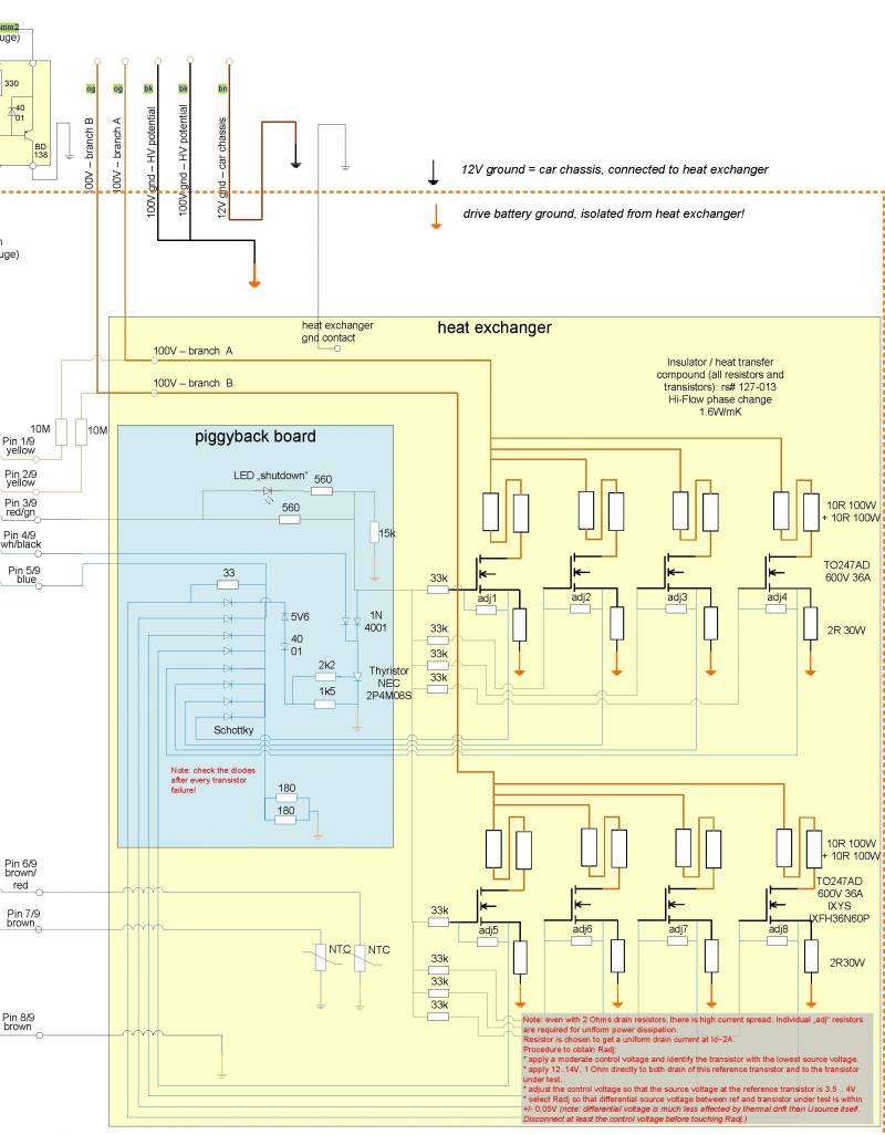
Below, for orientation only, a clipping of the wiring diagram. It will not indicate the peers of all connections, and it may be outdated. Please refer to above subchapter overview for a comprehensive and uptodate view.
The control voltage from pin 3 of the 9 pin connector (which is internal to the heater box) passes the piggyback board. Unless the emergency shutdown has engaged, the control voltage will be fanned out to the power transistors via 33k resistors. These resistors are required to avoid oscillation of the transistor group, and to allow for individual compensation of Ugs. The tedious procedure to determine the values of the “adj” resistors is described in the text box at the bottom of the diagram.
Each transistor provides a feed-back voltage from it's source terminal, that is in proportion to its drain current. The individual feedback voltages are collected on the piggyback board and combined by Schottky diodes. The sum signal is forwarded to the control unit via pin 5 of the 9 pin connector. During operation, the maximum voltage is 5 Volts. In case 6V are exceeded, the thyristor crowbar will trigger and cut short the control voltage, till the 12V supply voltage (=“heat on”) is reset. This status is indicated by a red LED on on the piggyback board.
The NTC temperature sensors connect to pins 6 and 7, respectively, of the 9 pin connector. The one isolated from the heat exchanger (indicated by the orange ground symbol, i.e. traction grid ground) connects to the control unit, while the one directly attached to the heat exchanger (purple ground symbol, i.e. car chassis ground) connects to the gauge in the dashboard.
isolator board
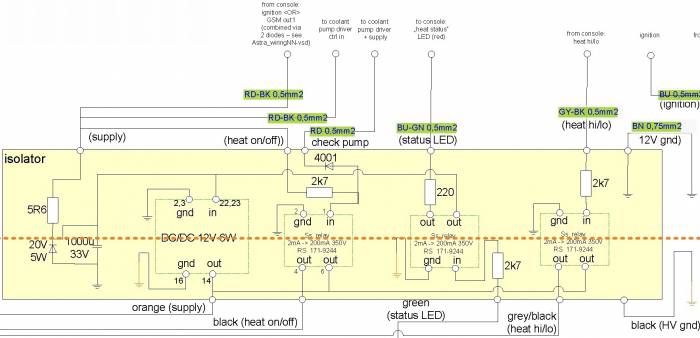
The isolator board comprises of a DC/DC converter for power supply of the control circuit (fed by the “heat on” switch in the dashboard) and three solid state relays that convey following signals:
- heat on/off (input): This is heat on/off signal from the dashboard, “AND” combined with the supply voltage for the coolant pump driver. In case the fuse of the coolant pump were blown or accidentially removed, the heater wont start.
- heater status (output): Conveying the status signal from the controller (actually a repetitive 8-bit sequence).
- heat hi/lo (input): This is the “heat hi” signal from the dashboard.
Below, for orientation only, a clipping of the wiring diagram. It will not indicate the peers of all connections, and it may be outdated. Please refer to above subchapter overview for a comprehensive and uptodate view.
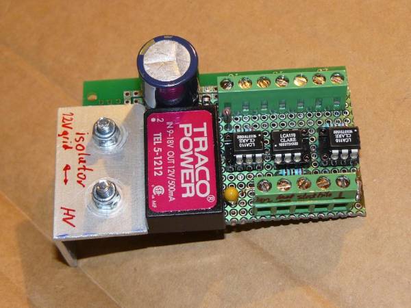
Top view of the isolator board.
control unit
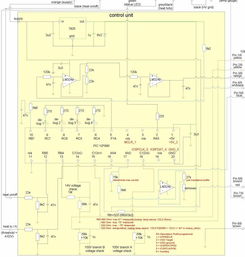
The control units controls the heater's output power in dependence of the two input signals (“heat on” and “heat hi”) and the heat exchanger's temperature. Additionally, it also checks the 12V and both 100V (traction grid) supply voltages. The control unit uses a “Microchip PIC 12F690” Microcontroller.
Below, for orientation only, a clipping of the wiring diagram. It will not indicate the peers of all connections, and it may be outdated. Please refer to above subchapter overview for a comprehensive and uptodate view.
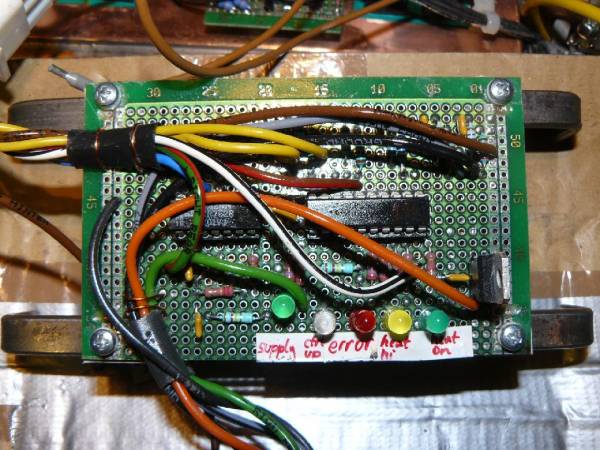
Top view of the control unit.
At pin 17, the “current” feedback voltage is sensed and A/D converted. Pin 16 senses the “temperature” signal. For the actual temperature, the corresponding target current is repetitively retrieved from a lookup table. If the target current is higher than the actual current, the control voltage is increased, else it is decreased.
Pin 5 delivers a pulse-width modulated output signal, from which the control voltage is derived in a two-stage lowpass filter. The filter consists of two RC circuits each followed by operational amplifier buffer stages.
A third operational amplifier is used for buffering the feed-back voltage from the source resistors.
For checking the supply voltages, three inputs of the controller's built-in voltage comparators are used.
For “heat hi” and “heat low”, there are dedicated lookup tables.
Below the calculated total power for the “high” lookup table in dependence of the heat exchanger temperature:
T [°C]        Ptot[Watts]


-51…………..0,0


-45………2180,0


0………….2180,0


10…………2180,0


20…………2180,0


30…………1962,0


40…………1744,0


50…………1526,0


55…………1417,0


60…………1308,0


65…………1199,0


70…………1090,0


75………….545,0


80……………..0,0


85……………..0,0


90……………..0,0
At the “high” power state, the heater (all FETs + resistors) will deliver 2180W up to a temperature of the heat exchanger of 20°C. The power will then be reduced down to 1090W at 70 degrees, and at 80 degrees it will be off completely (practically, it is now 83 degrees). Assuming a Rth junction-to-case of 0,19 and an Rth case-to-sink of 0,21 (guess, but critical parameter!), the maximum power per transistor will be 135 Watts, and the junction temperature will not exceed cosy 111°C. The drain resistors (100W, but with strong derating) will at maximum deliver 62,5 Watts at 20°C.
For the “heat low” lookup table, both the maximum power and maximum temperature are reduced to 1635W and 60°C, respectively.
In case of a fault such as emergency shutdown of the thyristor crowbar or low supply voltage detected on either branch, the controller will go into “fault” condition and signal this by different blinking patterns of the status LED:
- shutdown: 1000 0000
- 12V supply low: 1010 0000
- 100V supply branch A or B low: 1010 1000
In case of an unplausible voltage from the temperature sensor e.g. due to wire break, this is handled by respective “0” entries in the lookup tables.
code
The PIC code was written in Assembler, with the MPLab developer environment. Perhaps it may be helpful for someone working on a similar project. Please however don't expect too much of it, I am not at all a programmer!
coolant heater - assembler code. Press "Back" to return to this page.
temp gauge driver
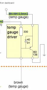
The output signal of this driver controls the temperature gauge in the dashboard. Since the heater runs at lower temperature than the engine did before, I have added the small driver circuit to adjust the gauge's scale. It consists of a PNP transistor working as an emitter follower, with a load resistor against ignition that determines the desired slope.
Please note that the output of the temp gauge driver circuit is not directly connected to the temperature gauge, but is looped over the controller board of the cooling system. In case the coolant heater is off, the temp gauge will display the temperature of the motor, else the signal from the coolant heater is relayed to the temp gauge.
mechanical setup
heat exchanger
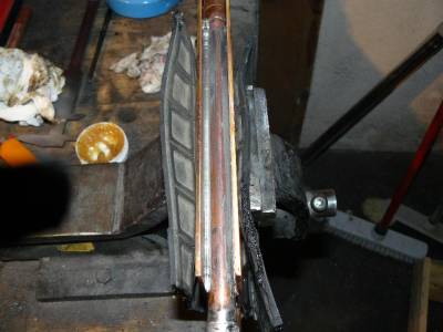
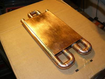
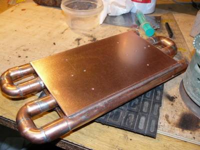
The heat exchanger consists of 4mm copper plates soft-soldered onto 19mm gauge copper pipes. It soon turned out that smaller pipes would have been much handier!
Most components were bolted into 4mm threaded holes. Fortunately, I never perforated the pipes.
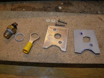
Isolated mount for the temperature sensor. As a heat transfer compound for all components, I first tried graphite silicone foil, which has temptingly good heat conductance…
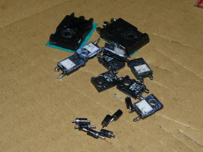
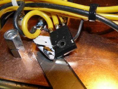
…but the mechanical resistibility of its isolating layer is very poor! At the very first test, the isolation of one transistor failed, and together with the bad design (no drain resistors) mentioned above, this cost a few component's lives.
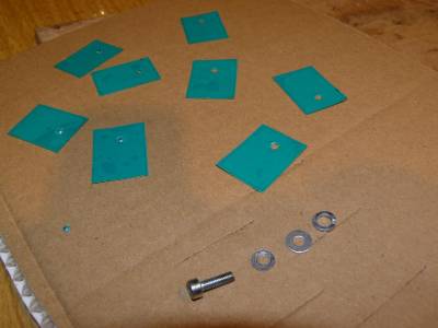
So I removed all the graphite silicon foil again …
… and replaced it by re-inforced phase-change compound material (Bergquist hi-flow300). The phase change material gets liquid at 55°C and so it fills any gap between component and heat sink. Note that usually the mount for the component has to be spring loaded to maintain the pressure while the component settles. I have only used spring washers that wont cover a larger displacement, but I have re-fastened all bolts after the first heating-up of the device. It turned out, that at the first heating-up, the components settled noticeably, but then no further re-fastening of the bolts was required.
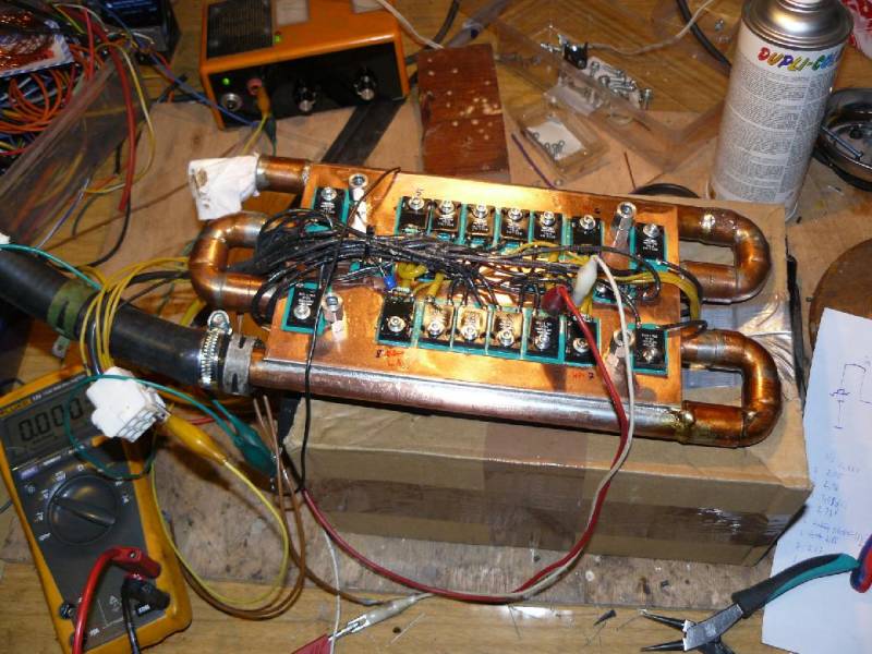
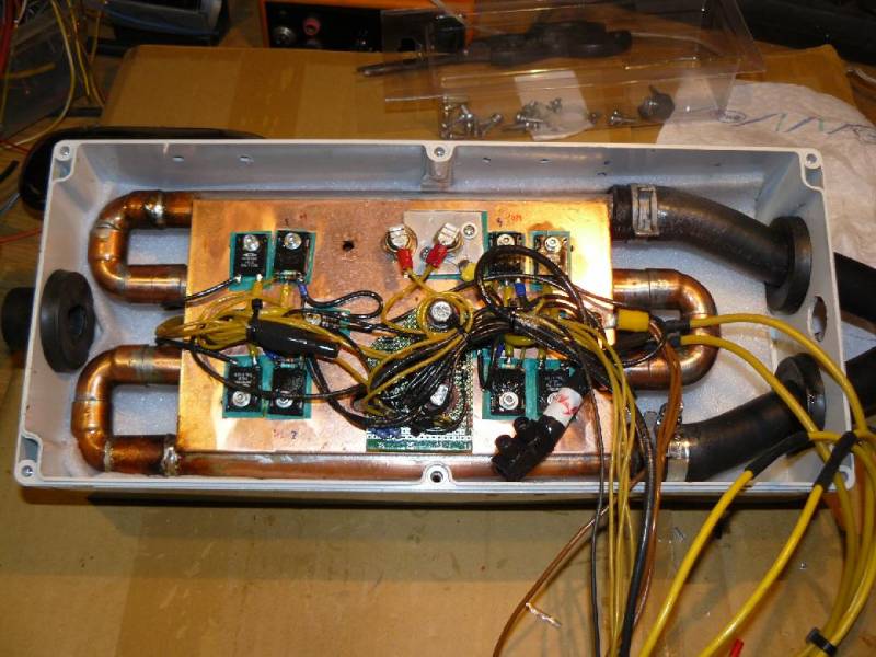
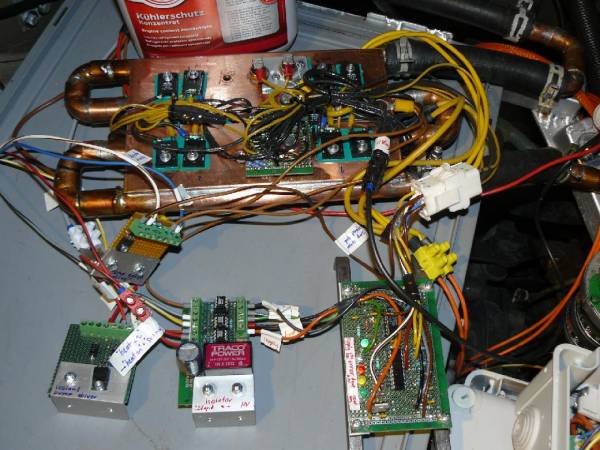
Finally, the heat exchanger is quite populated with components.
Here - you see it from the other side - it is already mounted into its polycarbonate box.
coolant circuit
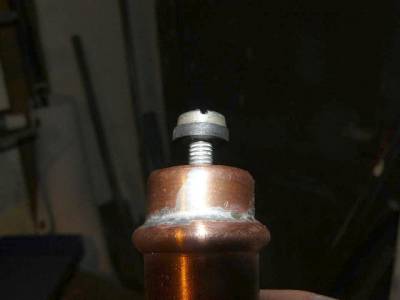
The coolant is circulated between the heater's heat exchanger and the dashboard heat exchanger by an electric pump. At the highest point, I have put in an “air trap”, at the lowest point, a thin hose branches off for draining the circuit. From the air trap, another hose connects to the car's original compensating reservoir.
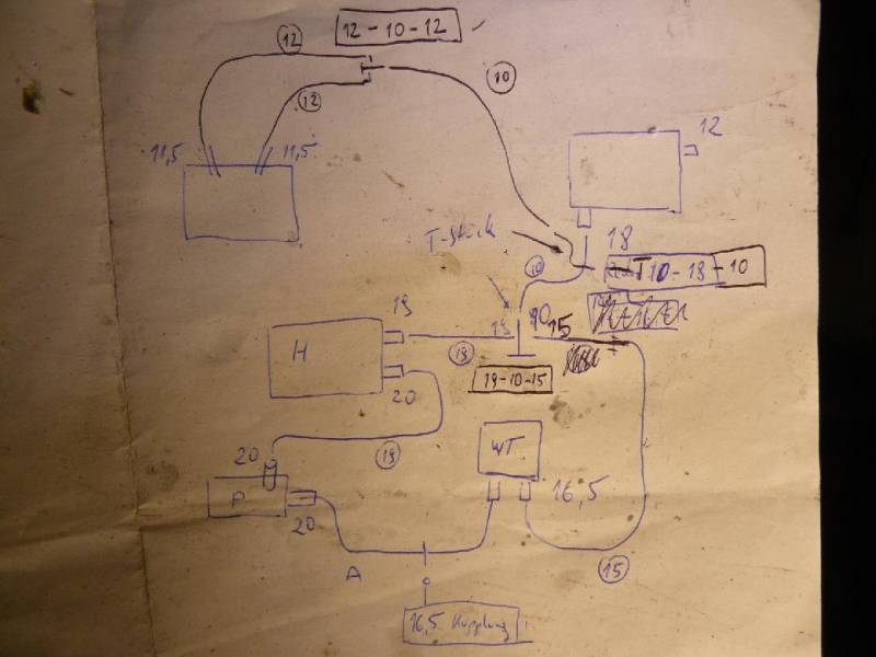
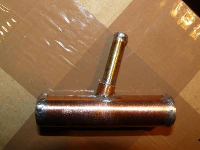
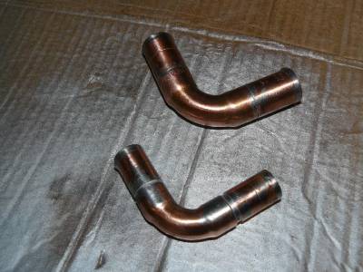
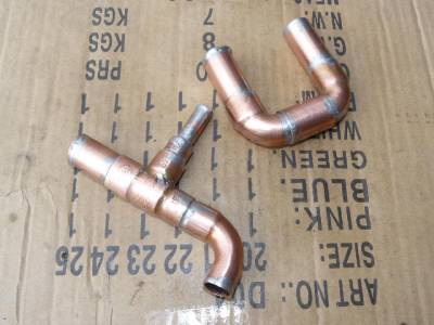
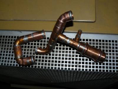
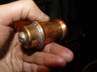
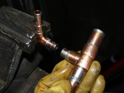
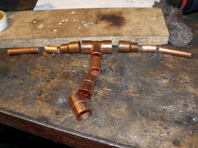
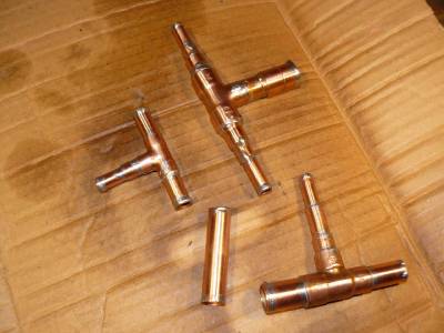
Since the components of the coolant circuit all require different hose diameters, a couple of adapters needed to be custom-made. Sketch of the adapters required. Note that the sketch is not uptodate: It does not contain the air trap yet. Furthermore, in the drawing, the traction motor (on the top left) is provisionally included. With the connections drawn, I only planned to test whether it is leakproof, cooling would not have been functional.
Ok, let's start! Another exercise in soldering …
I have to confess that my success rate for tight fittings turned out poor, quite some of them leaked and needed a second go.
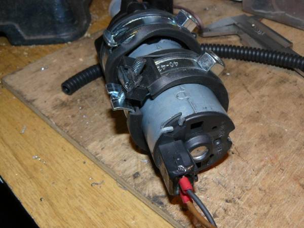
Coolant pump - Volkswagen T3 van drivers may recognize it! This model has a brushless DC motor, with only magnetic coupling between it's coils and the pump chamber, and appears quite durable.
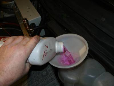
Filling up the reservoir. Since possibly the copper hoses electrically forced to chassis potential will build up electrochemical voltage against the dashboard heat exchanger, I will in future rather use blue (silicate based) than violet (organic) coolant liquid. The blue one needs to be replaced regularly, but it is recommended even for “aluminium vs. steel” constellations.
After filling the reservoir (1,5 liters of coolant liquid), the air cushion in the reservoir must be pressurized (0,5 atmospheres max.) via an external air pump. The pressure forces the liquid into the heater's coolant circuit. While filling up, the air must be slowly let out via the bolt on top of the air trap. Not all air will go out at once, and to complete the filling the pump must circulate the liquid for some time, while air pressure is maintained and excess air let out regularly.
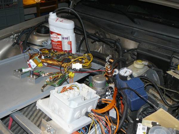
Draining the circuit is now easy, no crawling underneath the car, no spills any more! The plug in the end of the draining hose is removed, the end of the hose is put into a bottle, and (hopefully) the whole liquid is blown out by the cheapo air pump. In the picture, the pump (blue) can be seen in the right. The reservoir would be behind the right edge of the picture. The picture is from a test run, with the heat exchanger and related circuit boards loosely arranged in the left.
dashboard panel
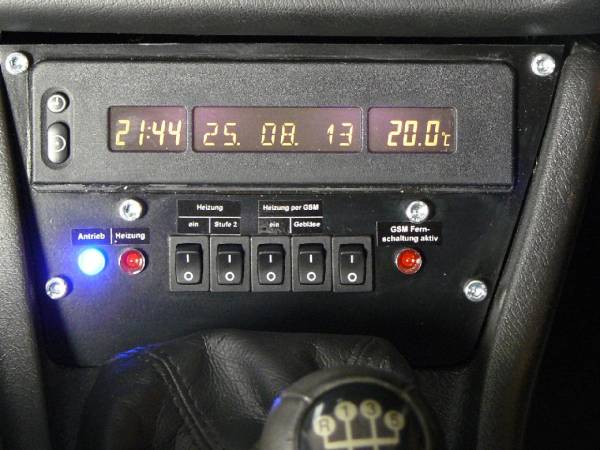
The coolant heater is controlled via switches in the central console of the dashboard panel. This was already mentioned in the “dashboard” section and when discussing the GSM module, but let me please comprise:
The blue light to the left indicates that ignition is on. In this case, the two switches to the left have effect:
- heat on
- heat hi: allows to choose between the two characteristic curves (heater current vs. coolant temperature) of the coolant heater control. Only when ignition is on, the heater may be switched to the “high power” stage.
The red light to the right indicates that the GSM remote control output “OUT1” is active. In this case, the other two (not counting the spare one) switches have effect:
- heat on
- blower on: The blower then will run at a fixed, low speed corresponding to position “2” of the knob on the dashboard central console.
If the heat is on due to either of the two ways, the red heat “status” LED will be lit, and signal the heater's status as described above in the chapter “control unit”.
- The fifth switch is reserved for an auxiliary air heater - in case the electric heater would later turn out to require support.
assembly
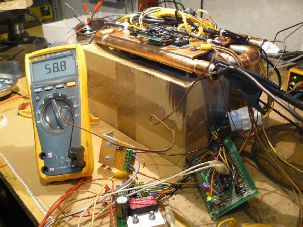
Here, the function of the controller circuit is being tested - the heat exchanger is still “dry” and run at low voltage. The actual temperature inside the heat exchanger is measured with the digital voltmeter plus temperature sensor.
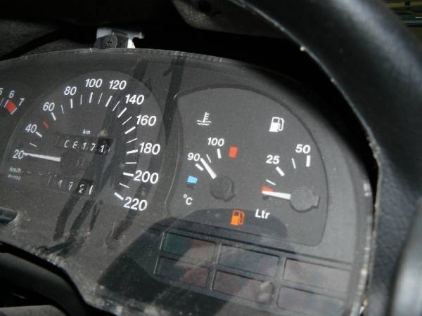
The temperature gauge in the dust-covered dashboard shows a higher temperature, which is intentional.
The components of the heater at the second test with circulating coolant and at 100V, reaching full power. No smoke this time!
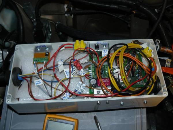
Here the heat exchanger is thermically insulated and all is (more or less) neatly arranged in the heaters' box.
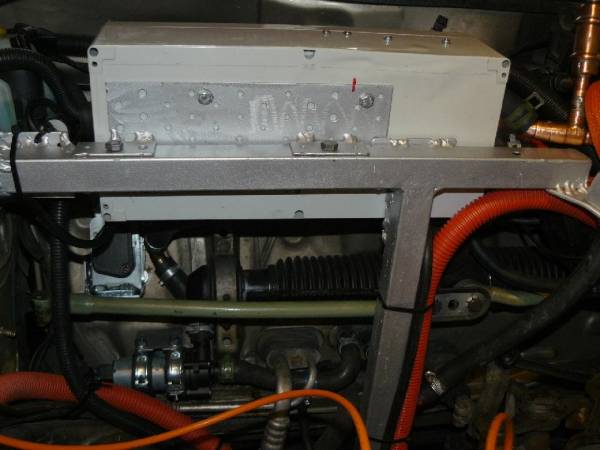
The box is mounted on the auxiliary frame via a mounting bracket. Below, you can vaguely discern the circulation pump.
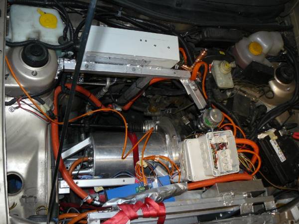
Overview: The heater box is in the top right. On the top right, we see the compensation reservoir. The “high voltage distribution” wiring box at the bottom of the picture holds the two 10A fuses that protect the two branches of the heater's power supply.

