Sidebar
astra_conv:conversion:current_rpm:current_rpm
Table of Contents
traction current gauge
functional description
I have been told that when driving an electric car, reading of the current (which is nearly proportional to electric power) is more useful than a reading of the motor's rotational speed. The rev meter (the term “tachometer” might be misleading in German) was unused anyhow after the conversion, so I made an adapter circuit that makes it now display the current on the traction circuit.
The battery computer does measure the current with its hall sensor and displays it as a digital number, but unfortunately it has no output for this measure. So, my adapter also has to sense the current in parallel.
The rev gauge is an electronic instrument that us usually connected to an electromagnetic sensor near the motor's flywheel. I found out that it could well be driven by a voltage source creating a 0..12V square wave, with 180 Ohms output impedance (I did not try other values, it just worked fine with this first “guess”).
The needle of the gauge starts moving away from its zero position at 10Hz, and reaches the top of the scale (7000 RPM) at 233Hz.
The functions of the adapter are:
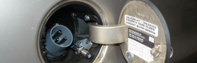
- sense the voltage drop along the negative rail of the traction circuit, using the connection from the engine compartment to the trunk as a “shunt” resistor.
- convert the absolute value of the sensed voltage drop into a proportional frequency.
- in addition, sense the polarity to drive an indicator for negative voltage drop (i.e. “recuperation”).
- provide electrical isolation between the potential of the traction circuit and the car's 12V grid.
circuitry
The circuit is located in the rear distribution box, as I wanted to avoid wires that carry “traction circuit” potential in the dashboard. It is mainly old-fashioned 1980s' stuff. I admit that making use of a microcontroller would have been more contemporary.
Circuit diagram. Again, the picture can be enlarged by clicking on it, or downloaded and viewed in an external viewer by right-clicking on the link below the picture.

link to wiring drawing (jpg), right-click and save as file (or directly open with a picture viewer)
All connections external to the appliance can be viewed in the overall wiring diagram - see chapter “wiring-general”
At the left edge of the diagram, there is one input for power supply (ignition) and one for connection to the sensed wire of the traction circuit, via 1 Amp fuses that are also located in the rear distribution box.
At the right edge, there is an output for the polarity indicator, which is connected to the “engine” warning lamp in the dashboard -a yellow lamp with an “engine” symbol on it, that was originally driven by the engine electronics.
The second output is the square-wave output that drives the rev gauge.
As in other circuit diagrams, the rectangle with dashed orange outline demarks the isolation barrier between traction grid and 12V grid. The sensed input is consequently on “traction circuit” potential, while all other terminals carry 12V grid potential.
power supply
Isolation is performed via a 12V DC/DC converter and solid-state optocoupler relais.
Below, for orientation only, a clipping of the wiring diagram. It will not indicate the peers of all connections, and it may be outdated. Please refer to above subchapter circuitry for a comprehensive and uptodate view.

amplifier / rectifier stage
Please refer to circuitry for a comprehensive and uptodate view.

As noted in the diagram, the trunk side end of the traction line is connected to (isolated) ground of the circuit, while the voltage at the other end is interpreted as “signal”. Therefore, a current flowing from the traction battery to the motor and back will create a signal of positive polarity.
In the first stage (operational amplifier “a”), the input signal is low-pass filtered and buffered by an operational amplifier. The stage also includes a potentiometer for offset compensation (affecting both following branches). With the large input impedance, I relied on the internal protection of the operational amplifier (while external diodes would somehow cause malfunction). The output of the first stage is once more lowpass filtered.
For the second stage, the signal is fanned out into a “positive” and a “negative” branch, i.e. a non-inverting (operational amplifier “b”) and an inverting (operational amplifier “c”) amplifier stage. On both branches, the amplification is adjustable with a target gain of 18 and -18, respectively. The negative branch has an additional offset compensation.
polarity detection
Please refer to circuitry for a comprehensive and uptodate view.

The output of the inverting stage is tapped into the “polarity detection” stage at the right top of the diagram. It's isolated output is buffered by a PNP transistor working as an emitter follower.
voltage controlled oscillator
Please refer to circuitry for a comprehensive and uptodate view.

But back to the signal path - the outputs of both amplifiers are combined via diodes. The resulting voltage is in proportion to the absolute value of the input signal.
The further circuitry on the right bottom of the diagram is a voltage controlled oscillator (somehow I could not find an integrated one, although I am sure there are - anyhow, it was a nice exercise).
The VCO stage's input voltage is transformed into a proportional current by the operational amplifier “d” and the BC548 transistor. The two BC558s form a current mirror that drains the same amount of current into the 100n capacitor. The “555” timer will discharge the capacitor when its voltage limits its upper threshold, which happens at a frequency proportional to the charging current.
The following “4013” dual D flip flop divides the frequency of these events by 4 and by this also obtains a symmetrical square wave. The following solid state relais directly drives the input of the rev gauge, which turned out to require only positive currents.
Circuit board of the current-RPM converter

calibration and test
The scale of the rev gauge ends at 7000RPM. The maximum current in the traction circuit may be somewhat below 350Amps. So, it appears sensible to have each 1000RPM correspond to 50Amps.
The expected voltage drop on the traction wire for a current of 350Amps can be calculated as follows:
The specific resistance of copper is 0.01786 Ohms*mm²/m. The resistance of 3.5m (estimated length) 50mm² gauge copper wire is consequently 0.00125Ohms → voltage drop at 350 Amps = 0,438V. So this should be the voltage corresponding to a read-out of 7000RPM. Note that for negative voltages, the circuit has a smaller range, its linear range will however at least go up to 175 Amps<> 3500RPM.
It is essential that for the wire that acts as a shunt resistor, no additional voltage drops can build up within joints and the cable lugs (if the cable lugs are used to join the traction cirucit wire ends with the thin “sensing” wires). In my opinion, only soldered joints will reliably (and sustained) have near zero resistance.
For adjustment of the potentiometers (gain and offset), it is best to simulate the voltage drop with a resistor bridge:

I have put together these instructions to easily reproduce the adjustment:
1) Apply 0V to the input (short-circuit): adjust “offset both” bottom left blue potentiometer)


	→ f out= 10Hz,


	(optional: U_LM324_pin14=0,3847V, extra blocking capacitor required pin14 - gnd,


	U_LM324_pin 8 =0,700V).


	for this step, voltage at pin 1 must not be higher than voltage at pin 8!


2) Apply 0V (short circuit): adjust “offset inv” (bottom right) → U_LM324_pin1=0,700V


3) Apply +0,438V: adjust gain non-inverting (top left) for 233Hz


4) Apply -250mV: adjust gain inverting (top right) for 134Hz
Rev gauge at 117Hz. It turned out that its linearity is surprisingly good, as it indeed shows 3500RPM (related to 7000RPM at 233Hz).

Recuperation - the yellow “engine” lamp is lit to indicate the reversed current flow, while the rev gauge again shows a positive value. The “oil” lamp indicates the “low voltage” alarm from the BMS (i.e. cell loop open - low voltage alarm of one or more cells). In the case of this photo, this was “false alarm” due to provisional batteries and wiring.

astra_conv/conversion/current_rpm/current_rpm.txt · Last modified: 2014/05/11 20:45 by richard
Except where otherwise noted, content on this wiki is licensed under the following license: CC Attribution-Share Alike 4.0 International
