Sidebar
astra_conv:conversion:traction_circuit:traction_circuit
traction circuit
Let's start with this circuit, as it can make the biggest sparks!
In the wiring_diagram, the traction circuit can be recognized by bold lines (i.e. wires with large cross-section). Note that however there are a few thick wires within the 12V grid as well.
The traction batteries are within the two battery boxes (orange), that are connected in series. Seven cells are in the front battery box, the remaining 23 cells in the rear box. The motor controller (pink box) is located in the blue “motor controller box”, together with with a dinky 425 Amps fuse and an electromagnetic contactor.
The motor controller connects to the motor via three thick wires. It also has connections to sensors within the motor, to the accelerator pedal and it has some control inputs served from the front distribution box.
The high-current connections are mostly done with 50mm2 stranded wire, mostly protected by ribbed tubes.
Below a view of the sub-floor cables. You will see that the wire pair of the traction circuit is twisted in order to reduce electromagnetic emission and susceptibility - communication engineers' voodoo. I have also, where evere possible, mounted the traction wires at a distance to all other wires to reduce interference. Anyhow, induction of quite some voltage peaks to the other wires has to be expected and must be taken care of.

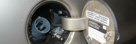
Another requirement of ECE R-100: All conductive parts that are related to the traction circuit and may be touched require a galvanic connection to the car's chassis. The photo e.g. shows the ground connection of the drivetrain (brown wire):

astra_conv/conversion/traction_circuit/traction_circuit.txt · Last modified: 2014/04/29 11:03 by richard
Except where otherwise noted, content on this wiki is licensed under the following license: CC Attribution-Share Alike 4.0 International
