astra_conv:conversion:dcdc_converter:dcdc_converter
Differences
This shows you the differences between two versions of the page.
| Both sides previous revision Previous revision Next revision | Previous revision Next revision Both sides next revision | ||
|
astra_conv:conversion:dcdc_converter:dcdc_converter [2014/03/17 21:31] richard |
astra_conv:conversion:dcdc_converter:dcdc_converter [2014/03/17 22:37] richard [how to spare the weight of the 12V lead-acid battery] |
||
|---|---|---|---|
| Line 78: | Line 78: | ||
| {{:astra_conv:conversion:dcdc_converter:p1110492.jpg?600|}} | {{:astra_conv:conversion:dcdc_converter:p1110492.jpg?600|}} | ||
| - | The current limiter is using the shroud as a heat sink (with additional cooling by the converter's air flow). | + | The current limiter utilizes the shroud as a heat sink (with additional cooling by the converter's air flow). |
| - | {{:astra_conv:conversion:dcdc_converter:p1110591.jpg?300|}} | + | {{:astra_conv:conversion:dcdc_converter:p1110591.jpg?600|}} |
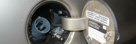
| On the right, the opened 100V distribution box can be seen, with primary side fuse and the terminal area of the DC/DC converter primary driver. The output relay is hidden below in the front 12V distribution box. | On the right, the opened 100V distribution box can be seen, with primary side fuse and the terminal area of the DC/DC converter primary driver. The output relay is hidden below in the front 12V distribution box. | ||
| - | One device had failed at low temperature. Now, my DC/DC converters have to undergo the harsh and very professional "deep freeze" test. | + | {{:astra_conv:conversion:dcdc_converter:p1110595.jpg?600|}} |
| + | |||
| + | One device had failed at low temperature. Now, my DC/DC converters have to undergo a harsh and highly professional "deep freeze" test, to prove that they do start up at -18 degrees Celsius. | ||
| {{:astra_conv:conversion:dcdc_converter:p1110482.jpg?600|}} | {{:astra_conv:conversion:dcdc_converter:p1110482.jpg?600|}} | ||
| + | |||
| + | \\ | ||
| + | |||
| + | ==== how to spare the weight of the 12V lead-acid battery ==== | ||
| + | |||
| + | In principle, it would be possible to keep the DC/DC converter on permanently, or to add a second, smaller device that feeds the 12V grid while the car is idle. | ||
| + | |||
| + | An additional, small DC/DC converter could be optimized for prolonging the battery life by doing all that ctek rituals of switching between different charging phases at different voltages. I am imagining to use a small 15V output DC/DC converter module as a power supply, followed by a microcontroller circuit that fine tunes the output voltage. | ||
| + | |||
| + | With a permanent power supply, the battery is not drained any more while the car is idle, and it's size can be substantially reduced. | ||
| + | |||
| + | The extreme case would be to omit the 12V battery at all. Of course, without a battery, it must be ensured that at any time that the DC/DC converter can deliver sufficient current to feed all 12V consumers. Especially for the anti-lock brakes, I am however not so sure about their peak current drain. A 12V battery will also come in handy as a back-up supply when the traction circuit is interrupted (maintenance) or when the DC/DC converter is broken. | ||
| + | |||
| + | So, it is probably the best option to keep the 12V battery, and only make it smaller. Unfortunately, batteries below some 40Ah dont have proper sockets, so a mechanical adapter bracket will be required. | ||
| + | |||
| + | |||
| + | |||
| + | |||
| + | |||
| + | |||
| + | |||
| {{actionlink>top|*** back to top of this page ***}} | {{actionlink>top|*** back to top of this page ***}} | ||
astra_conv/conversion/dcdc_converter/dcdc_converter.txt · Last modified: 2014/06/20 13:02 by richard
Page Tools
Except where otherwise noted, content on this wiki is licensed under the following license: CC Attribution-Share Alike 4.0 International
