astra_conv:conversion:controller_box:controller_box
Differences
This shows you the differences between two versions of the page.
| Both sides previous revision Previous revision Next revision | Previous revision | ||
|
astra_conv:conversion:controller_box:controller_box [2014/05/09 15:53] richard |
astra_conv:conversion:controller_box:controller_box [2014/05/11 20:44] (current) richard |
||
|---|---|---|---|
| Line 13: | Line 13: | ||
| {{ :astra_conv:conversion:distribution_boxes:w_controller_box.jpg?330 |}} | {{ :astra_conv:conversion:distribution_boxes:w_controller_box.jpg?330 |}} | ||
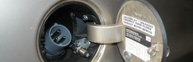
| - | The large black box is the motor controller itself. | + | The box at the bottom is the motor controller itself. |
| Supply from the traction battery is switched via a small relay that drives the large contactor. | Supply from the traction battery is switched via a small relay that drives the large contactor. | ||
| - | The three orange 50mm² gauge wires connect to the motor. | + | The three orange 50mm² gauge wires connect to the motor as shown in the next picture. |
| {{:astra_conv:conversion:distribution_boxes:w_motor.jpg?320|}} | {{:astra_conv:conversion:distribution_boxes:w_motor.jpg?320|}} | ||
| Line 25: | Line 25: | ||
| - | The controller connects to the accelerator potentiometer (described in the next section) and to rotation and temperature sensors in the motor. | + | The controller connects to the accelerator potentiometer (described in the next section) and to position and temperature sensors in the motor. |
| - | A couple of additional control wires go from the motor controller box to the 12V distribution box. Since some of the wires are on traction grid potential, they require decoupling by relays - as e.g. the immobilizer relay or the solid state relay that conveys the signal from the brake pedal switch. | + | A couple of additional control wires go from the motor controller box to the 12V distribution box. Since some of the contacts are on traction grid potential, exchanging signals to and from the 12V grid requires decoupling by relays. Such relays (both located in the 12V distribution box) are e.g. the immobilizer relay or the solid state relay that conveys the signal from the brake pedal switch. |
| \\ | \\ | ||
| Line 33: | Line 33: | ||
| ===== motor controller setup ===== | ===== motor controller setup ===== | ||
| - | The motor controller can be configured via an external hand-held device. This device allows to modify a set of parameters, that widely determine the controller's characteristics. Please see the section [[astra_conv:conversion:drivetrain:drivetrain#drivetrain]] and the chapter "driving the electric Astra" for details! | + | The motor controller can be configured via an external hand-held device. This device allows to modify a set of parameters, that widely determine the controller's characteristics. |
| + | |||
| + | At low RPMs, the secondary current (i.e. the current between controller and motor) gets very high even at low primary (traction battery) current. If the controller settings are not carefully optimized, the controller tends to either temporarily go into "current limiting" mode and reduce the power, or to unexpectedly switch off completely. | ||
| + | |||
| + | The controller manufacturer finally provided Marco and me with a configuration "optimized for performance" that makes the motor deliver a lot of torque from 0 rpm on (like the datasheet would suggest anyhow) and avoids shutdowns. It is however still required to press the pedal with care to avoid uneven acceleration when the current limiter kicks in. Apparently, although it is rated for 500 Amps (secondary current however), the controller here comes to its limits. | ||
| + | |||
| + | |||
| + | Besides a lot of parameters that control the motor characteristics itself, there is a couple more settings e.g. for setting the characteristics of regenerative braking. | ||
| + | |||
| + | Three different kinds of "braking" can be distinguished: | ||
| + | "directional brake" avoids that the motor too easily spins backwards after stopping on a slope | ||
| + | "neutral brake" provides gentle braking when the accelerator pedal is released | ||
| + | "foot brake" provides additional braking when the brake pedal is pressed. | ||
| + | |||
| + | Practically, it is required to provide both "neutral brake" and "foot brake", so that the deceleration builds up in two steps. | ||
| + | |||
| + | For all kinds of brake, ramp-up times can be configured. For neutral brake and foot brake, I have finally configured ramp times slightly above two seconds, to get a smooth start and end of the deceleration phase. A delayed start of braking also facilitates switching, especially for old-fashioned people who still cling to the old habit of double-clutching. | ||
| {{actionlink>top|*** back to top of this page ***}} | {{actionlink>top|*** back to top of this page ***}} | ||
astra_conv/conversion/controller_box/controller_box.1399650801.txt · Last modified: 2014/05/09 15:53 by richard
Page Tools
Except where otherwise noted, content on this wiki is licensed under the following license: CC Attribution-Share Alike 4.0 International
